Isolation is not needed, therefore I have chosen to use a nonisolated (e.g., ``3 terminal'') integrated switching regulator. In particular, I selected the PowerTrends PT6302 (3 amp ISR) which is much more efficient than the isolated regulators (e.g. Datel, etc.). Not only does this result in extended battery life, but also much less heat is produced by it.
WearComp6 is generally built from the Ampro CoreModule, together with various other modules. Most of the other modules do not have a power connector; power is connected only to the CoreModule, and the other boards derive their power through the interconnecting pins. The CoreModule has a 10 pin (or on some older versions, an 8 pin) power connector. The power connector provides both 5 volt and 12 volt connection terminals. However, most modern boards do not require the 12 volt connection, so you generally only need to connect 5 volts to the core module.
It is generally worth the extra money to get the CoreModule development system (e.g. the version that comes with all the connectors), especially if this is the first unit you build. Subsequently this gives you time to track down the sources for the various connectors, yet still lets you make sure you have a ``stock'' reference system to compare against cables you make up yourself.
Included in the CoreModule development system, you will generally find the power connector (e.g. MX40 or the like), with a 10 (or 8) pin female connector -- 2 rows of 5 (or 4) to mate with the header pins on the CoreModule. See Fig 3.
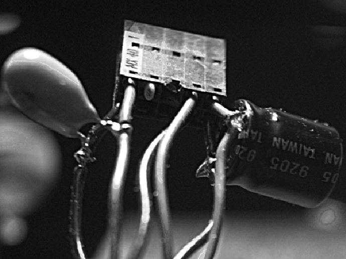
Figure 3: The power connector mates with 10 pins
(some versions are made to mate with only 8 pins).
Here I have used all three pairs of 5 volt wires.
Note the key pin (right next to the ``MX 40'' designation)
which is marked by a triangular ``arrow''. Note also the
two additional capacitors (one electrolytic, and one tantalum
which has lower effective series resistance than electrolytic)
which I have added as close as possible to the connector.
These are optional, and arise from my healthy level of
power spike paranoia.
You can cut off the 12 volt wires. You might also be inclined to think that some of the 5 volt wires are redundant (e.g. there are 3 pairs of wires for 5 volts). However, it is important to use all 3 pairs; I found using all 3 pairs gave rise to greater system reliability. Furthermore, position the ISR in such a way as to minimize the lead length going to the power connector. The lead-length and actual layout will depend on the specific enclosure you build or purchase.
Originally, I built my own enclosures using sheet metal
and a metal bending
machine![]() .
If you have access to a metal
bending machine, this is quite easy to do; first draw the spread-out
design on paper, then glue the paper to sheet metal (typically
aluminum), and cut with the machine, then bend appropriately.
.
If you have access to a metal
bending machine, this is quite easy to do; first draw the spread-out
design on paper, then glue the paper to sheet metal (typically
aluminum), and cut with the machine, then bend appropriately.
Here, however, I will illustrate putting together a system using a commercial off-the-shelf enclosure, for the benefit of those who do not have a metal bending machine or the like. The most suitable enclosure is the so-called ``half cube enclosure'' which can be obtained from Enclosure Technologies Inc (ETI), distributed by Tri-M (http://www.tri-m.com/). Tri-M also sell many other PC104-related products.
With the ``half cube enclosure'', you can easily keep the power cables 2 inches or less in length. (I found, for example, that the original 6 inch power cable was unreliable due to this excessive length.) The connection from the power cable to the ISR is shown in Fig 4.
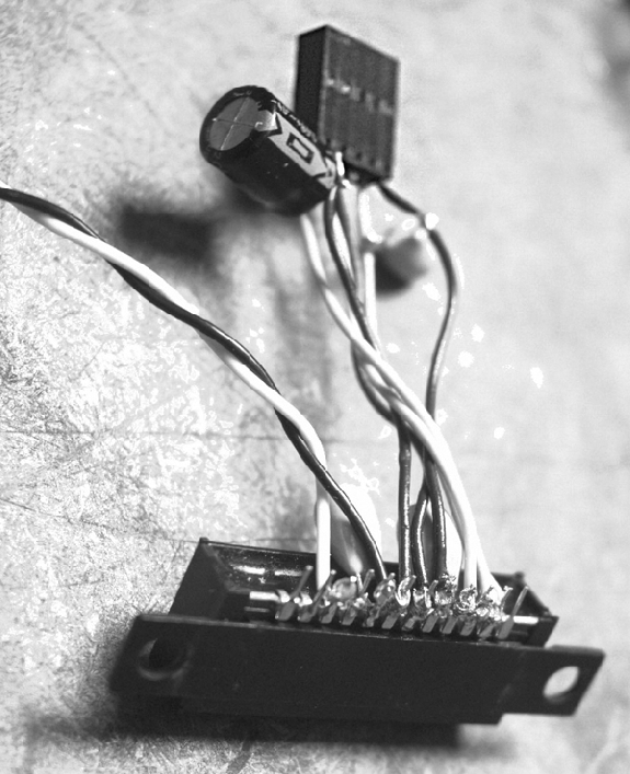
Figure 4: All three pairs of 5 volt wires may be connected to
the various parallel pins of the pt6302 ISR. In particular
the ISR also has three ``redundant'' +5 volt pins.
Connect one of each red wire from the power cable to
each of these. The ISR has four ``redundant'' ground
pins. Connect the three black wires from the power cable
to three of these. That leaves one ground connection
for the 12 volt input to the ISR (higher voltage
and correspondingly less current). Connect a single
twisted pair of wires to the input (conductors do not
need to be so thick owing to the lesser current, as well
as the fact that the ISR will make up for line losses).
Make sure that the twisted pair of wires has
tough insulation as this will be outside the enclosure and
subject to wear and tear. Here I used a 100![]() f output
capacitor and a 47
f output
capacitor and a 47![]() f input capacitor with leads soldered
to the appropriate pins of the ISR for additional filtering.
It is desirable to select an input capacitor which has a high
enough voltage rating to match the range of
input voltage that the pt6302 can handle, since this will allow you
to run the rig on a wider range of input voltages.
f input capacitor with leads soldered
to the appropriate pins of the ISR for additional filtering.
It is desirable to select an input capacitor which has a high
enough voltage rating to match the range of
input voltage that the pt6302 can handle, since this will allow you
to run the rig on a wider range of input voltages.
The next step is to mount the ISR inside the enclosure. The reason for mounting it solidly inside the enclosure is twofold:
The optimal place to mount it in the `half cube' is on the bottom of the enclosure, near the front, and toward the left. This location was selected for three reasons:
Begin by marking and drilling holes for the ISR. Once these holes are drilled, and once all other holes that you think you will want in the case are drilled, clean off all debris (metal flakes, etc.) and proceed to put the nylon standoffs into the case (for anchoring the board stack). Other holes you may wish to drill are wire tie holes for mounting the hard drive (read ahead to next section). Line the bottom of the case with heavy cloth tape, leaving space for the ISR (this is more healthy paranoia -- just to make sure nothing could short to it). See Fig 5.
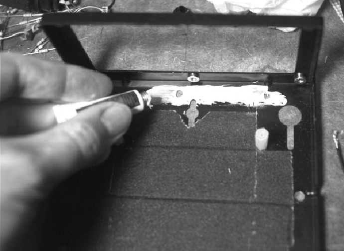
Figure 5: Once the bottom of the ``half cube enclosure'' is lined with
cloth tape, heatsink compound is applied where the ISR will go.
Note that I have removed the front of the enclosure (held on with
six screws) for easier access later on when it comes time to
insert the ISR.
Once you have proceeded this far (lining the bottom) you should not drill any more holes in the case, or debris (metal flakes, etc.) may become stuck to the cloth tape. Next apply heatsink compound to install the ISR.
The pt6302 ISR comes in six variations, with and without mounting tabs (select the one with mounting tabs), and each of these comes in three variations (horizontal mount, surface mount, and vertical mount). Vertical mount is preferable, but often out of stock. The most readily available is surface mount, and this would otherwise create a problem as the pins would touch the case, but a small aluminum shim will fix this problem and keep the pins sufficiently far away from the case. Fig 6 shows the ISR installed with a shim I made from 1/8 inch aluminum.
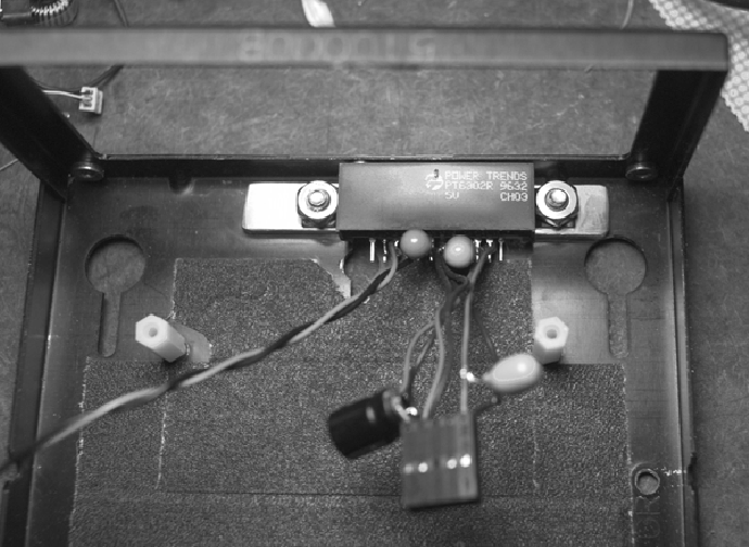
Figure 6: The pt6302 ISR is installed near the front of the enclosure,
facing inwards. Locate it so that the power cable emanates
from directly below where the power connector is located on
the PC104 CoreModule. Note the aluminum shim I have bolted
underneath the ISR to keep the pins from touching the case.
Be careful not to locate objects near
pin 12 (the sense pin) of the ISR. For example, if the
disk cable comes too close to pin 12, stray emissions will
affect the computer and make it unreliable. Touching pin
12 when the computer is running will generally cause a spike
of sufficient strength to reboot the computer. If you don't
need it, you might consider breaking it off or cutting it short
so it doesn't act like a receive antenna.
Bring the 12 volt power leads out of the enclosure, thread through a ferrite bead if you like (more healthy paranoia), and then solder on banana plugs (red and black) for connection to power later.